Apollo CSM Propulsion Redesign Trade Study
From helium pressure-fed to turbopump: decoupling chamber pressure from tank pressure
- Role
- Team of five — I led the feed-system redesign, parametric analysis, and turbopump CAD
- Status
- Completed
Headline results
The baseline and what it costs
The Apollo Command and Service Module's Service Propulsion System used the Aerojet AJ10 — a bipropellant engine burning N₂O₄ and Aerozine-50, rated at 20,500 lbf, responsible for lunar orbit insertion and departure. It was designed to be extremely reliable, and it achieved that reliability partly through a helium pressure-fed architecture.
Pressure-fed systems, though, push tank pressures upward to achieve acceptable chamber pressure, and tank pressure drives tank mass. The pressure budget is unforgiving: tank pressure has to support chamber pressure plus injector and line losses.
Tank mass grows with pressure and with size, and the helium system adds further dry mass through high-pressure bottles, regulators, and plumbing. Raising chamber pressure to gain performance therefore costs mass twice over in a pressure-fed architecture.
The turbopump concept
A turbopump feed system decouples chamber pressure from tank pressure. Tanks can be kept at relatively low pressure — chosen for inlet conditioning and cavitation margin rather than for chamber pressure — while the pumps raise propellant pressure to what the injector and chamber require.
Parametric results
For a fixed mission Δv, required propellant mass depends on both specific impulse and dry mass. Working through the rocket equation across candidate chamber pressures separates those two contributions.
| Design | P_c | I_sp (s) | %Δu_e | m_f (kg) | m_p (kg) | %Δm_p |
|---|---|---|---|---|---|---|
| Baseline (pressure-fed) | 0.69 MPa | 314 | 0.0% | 6,100 | 9,044 | 0.0% |
| Turbopump + low tank pressure | 1 MPa | 320 | 1.9% | 5,025 | 7,239 | −19.9% |
| Turbopump + low tank pressure | 3 MPa | 330 | 5.1% | 5,025 | 6,912 | −23.6% |
| Turbopump + low tank pressure | 5 MPa | 333 | 6.1% | 5,025 | 6,819 | −24.6% |
| Turbopump + low tank pressure | 6 MPa | 335 | 6.7% | 5,025 | 6,759 | −25.2% |
The result worth reading carefully is the gap between the two percentage columns. Raising chamber pressure by nearly an order of magnitude buys only a few percent in exhaust velocity — that is real but modest. The large propellant saving comes from the dry-mass reduction that low tank pressure enables, dropping final mass from 6,100 kg to 5,025 kg. Attributing the whole 25% to specific impulse would be the easy mistake, and it would be wrong.
We designed to 5.5 MPa chamber pressure, which sits at the knee of the curve: nearly all of the available propellant saving, without pushing pump and chamber requirements further for the last fraction of a percent. The matching nozzle for ideal expansion at that chamber pressure sizes to an area ratio of about 62.
CAD and routing
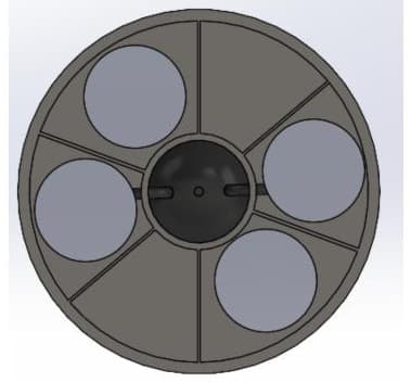
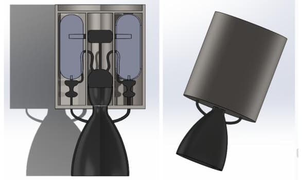
The bipropellant system CAD was built jointly with a teammate: I did the turbopump inclusion and propellant-line routing, and my teammate handled tank resizing. The routing is where the architecture becomes concrete — the pump inlets, the discharge lines to the injector, and the preburner gas path that drives the turbine all have to physically fit within the Service Module envelope.