Aircraft Wing Structural Optimization
Shell finite-element modeling and parametric optimization under deformation and stress constraints
- Role
- Team of three — thickness studies, mathematical model, and optimization
- Status
- Completed
Headline results
The problem
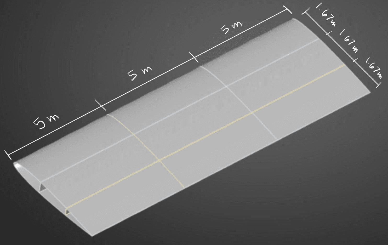
Aircraft wing structures balance strength, stiffness, and weight. Excess structural mass reduces aerodynamic efficiency and increases fuel consumption; insufficient stiffness or strength leads to excessive deformation or failure under load. The objective here was to minimize the mass of a simplified thin-walled wing — skin, spars, and ribs, cantilevered and loaded by aerodynamic pressure plus gravity — subject to a maximum deformation of 0.375 m and a maximum von Mises stress of 252 MPa.
Why shell elements
For thin-walled components the characteristic thickness is much smaller than the in-plane dimensions, so the three-dimensional continuum can be accurately represented by its mid-surface with thickness carried through the constitutive relations rather than resolved geometrically. This drops the degree-of-freedom count sharply while retaining the dominant bending, membrane, and transverse shear behaviour.
The structural response follows from the principle of minimum total potential energy, π = U − W. For a shell, strain energy integrates membrane strains, bending curvatures, and transverse shear strains over the mid-surface, with membrane, bending, and shear stiffness matrices assembled from Young's modulus, Poisson's ratio, and thickness. Bending stiffness scales with t³ while membrane stiffness scales linearly with t — which is precisely why thickness is such a powerful design variable, and why the response surfaces later come out so strongly nonlinear.
Baseline and mesh sensitivity
The initial design — 1 rib, 2 spars, 10 mm skin, 10 mm ribs, 10 mm spars, 4,768 kg — failed both constraints, deforming 0.8168 m against the 0.375 m limit and reaching 309 MPa against the 252 MPa limit. That baseline is the reference point for everything that follows: the optimization is not making a working design lighter, it is finding the lightest design that works at all.
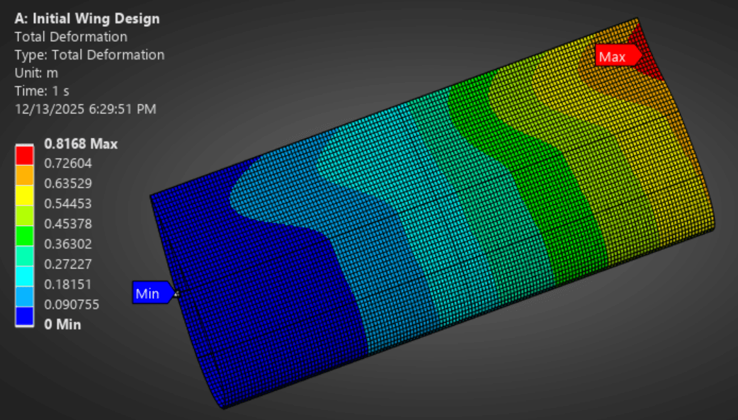
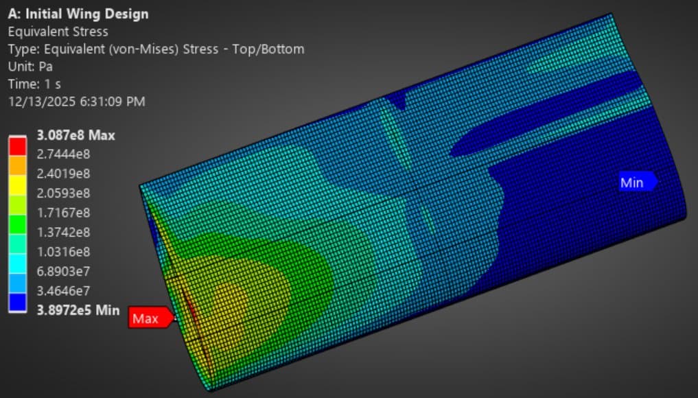
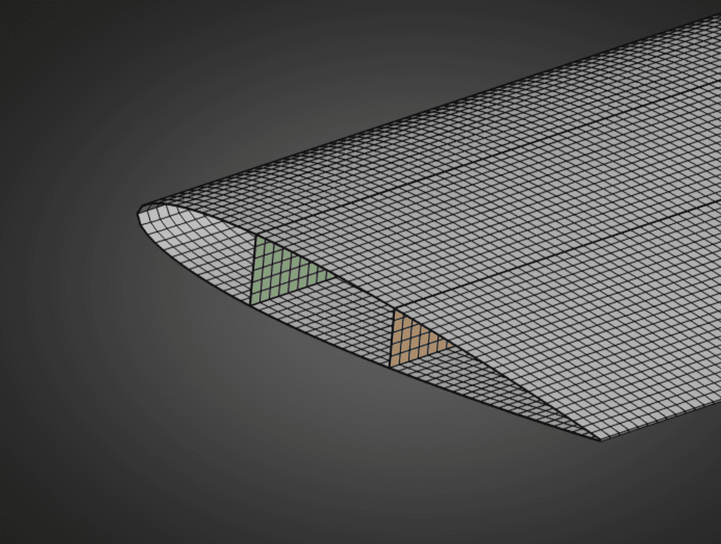
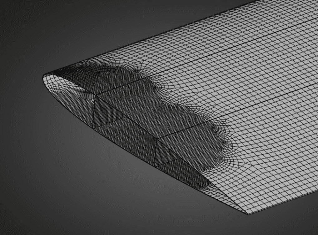
Before trusting any optimum, we ran a mesh sensitivity study to separate real stress concentrations from discretization singularities. This matters more than it sounds: a stress singularity at a re-entrant corner will keep rising as the mesh refines and never converge, and an optimizer chasing it will keep adding material to a location that is a modeling artifact.
Parametric optimization
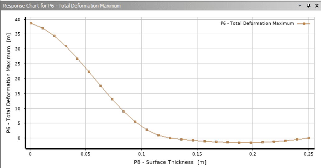
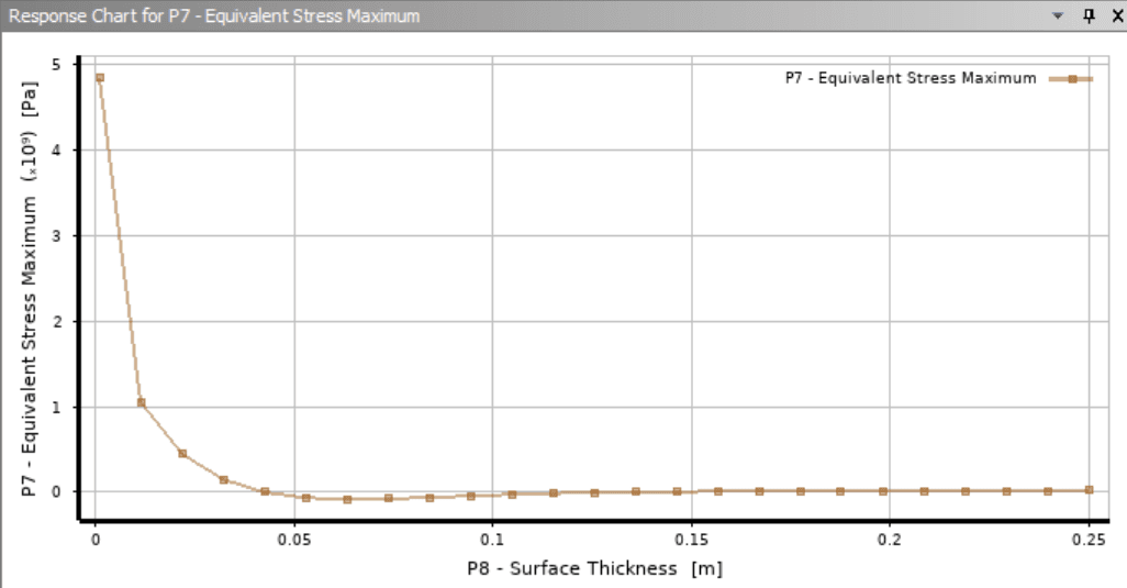
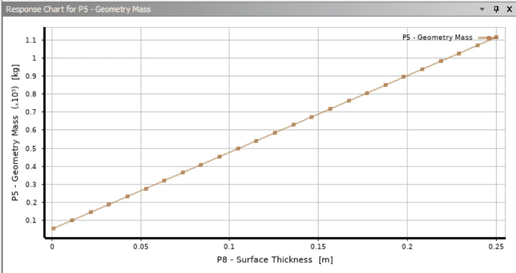
With geometric mass, maximum total deformation, and maximum equivalent stress set as output parameters, the single-parameter study swept skin thickness alone. The candidate point came back at 0.01885 m skin thickness for 8,533 kg — heavier than the baseline, which is exactly right, because the baseline was infeasible. The response charts confirm the expected behaviour: mass rises linearly with skin thickness while deformation and stress fall off sharply.
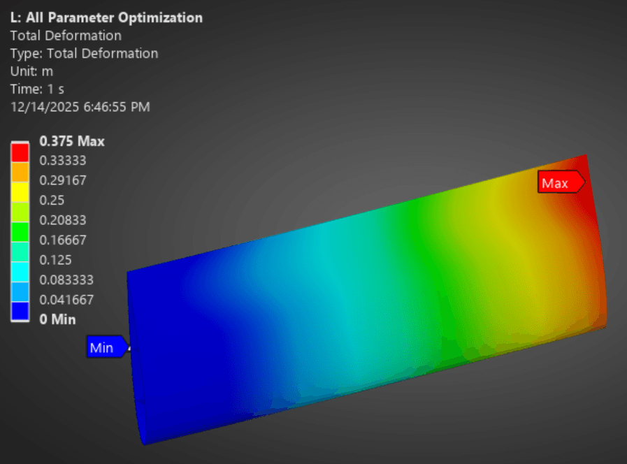
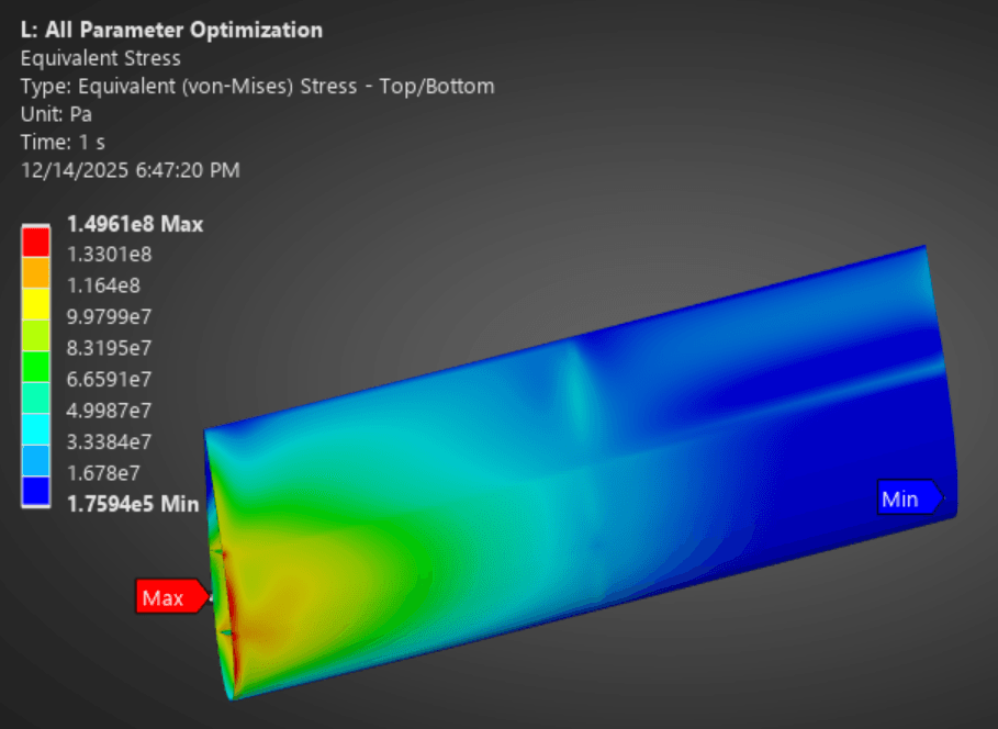
Opening skin, rib, and spar thickness together brought mass down to 8,384.6 kg at 0.375 m deformation and 150 MPa stress — a better result, and the first indication that the design is deformation-controlled rather than stress-controlled.
Design exploration: rib and spar layout
Knowing the model was deformation-controlled, we bounded maximum deformation between 0.36 m and 0.37 m to sit just inside the 0.375 m limit, capped stress at 252 MPa, and minimized mass across ten evenly-spaced rib and spar configurations.
| Variation | Ribs | Spars | Skin (m) | Mass (kg) | Max def. (m) | Max stress (MPa) |
|---|---|---|---|---|---|---|
| Initial | 1 | 2 | 0.0100 | 4,768 | 0.8168 | 309 |
| 1-parameter | 1 | 2 | 0.0188 | 8,533 | 0.368 | 148 |
| 3-parameter | 1 | 2 | 0.0185 | 8,385 | 0.375 | 150 |
| C | 1 | 1 | 0.01948 | 8,586 | 0.3747 | 168 |
| D | 1 | 3 | 0.01635 | 8,198 | 0.3747 | 161 |
| E | 2 | 1 | 0.01873 | 8,329 | 0.3282 | 149 |
| F | 3 | 1 | 0.01885 | 8,466 | 0.3750 | 170 |
| G | 2 | 2 | 0.01778 | 8,121 | 0.3749 | 169 |
| H | 3 | 2 | 0.01845 | 8,091 | 0.3747 | 192 |
| I | 2 | 3 | 0.01823 | 8,006 | 0.3749 | 196 |
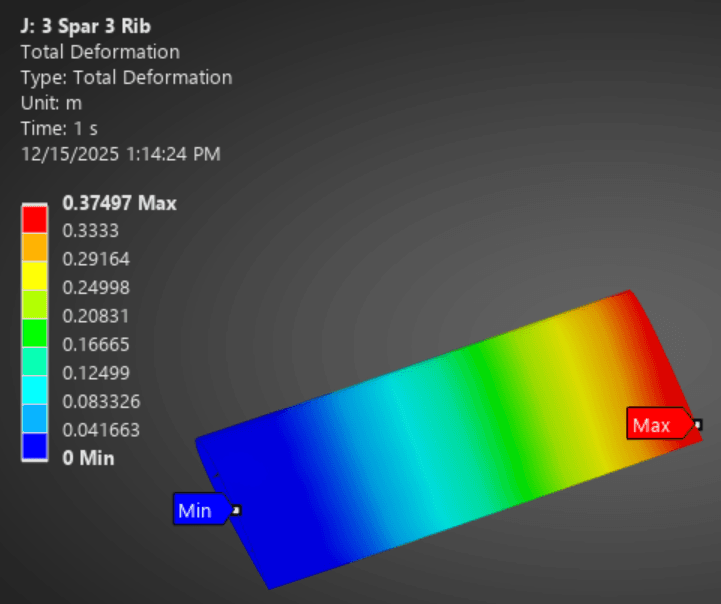
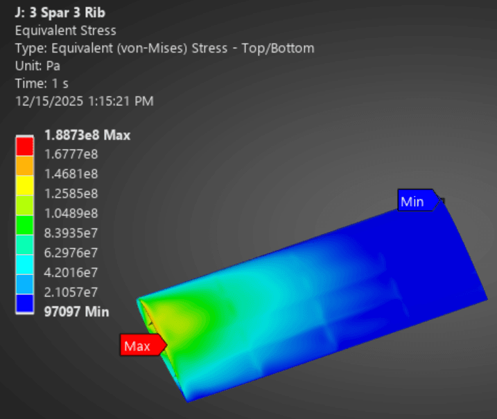
| J (recommended) | 3 | 3 | 0.01804 | 7,967 | 0.37497 | 189 |
Conclusion
Design J — three ribs, three spars, 18.04 mm skin, 3.094 mm ribs, 3.897 mm spars — reaches 7,967 kg while staying inside both the 0.375 m deformation and 252 MPa stress limits. Across every study the same trend held: more ribs and spars let us reduce total deformation while thinning every member. Because the design is deformation-controlled, the optimum is the configuration with the most internal structure.